 Enhanced IO - Connecting
USB MPVI Pro Interface Only
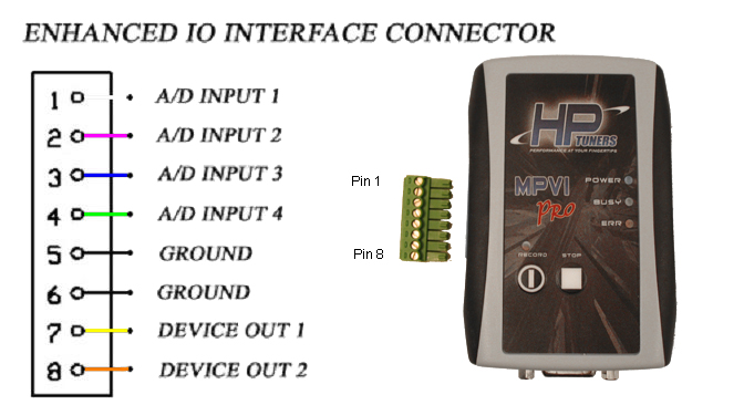
Serial Interface Only

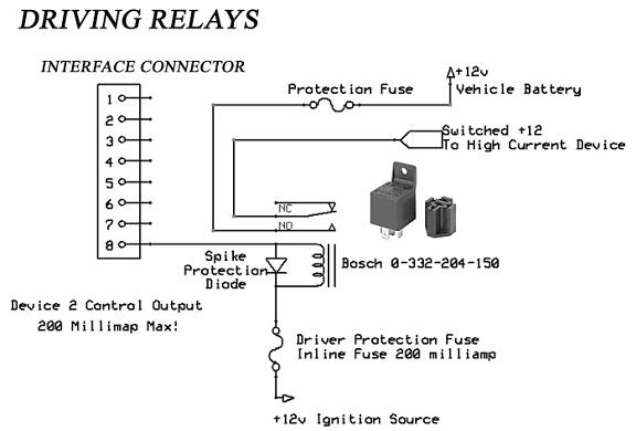
Sample Relay Circuit
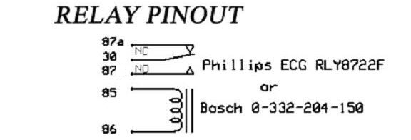
The Following circuit uses a Bosch Automotive Relay
Part Number 0-332-204-150
When and how the relay(s) turns on and off by tracking any engine
variable or A/D channel value is configured in the VCM Scanner
program. They can be used as a status indicator or external high
current device control. NEVER use the interface to control relays
where safety is an issue or vehicle damage may occur.
Do not forget to add the driver protection fuse.
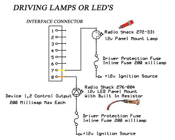
Sample Light Circuit
The Following circuit uses a Radio Shack 276-272 12v Led with built
in resistor and a Radio Shack 272-331 Panel Lamp using the supplied
pigtail connector. Both lights come in their own ready to mount
housing.
When the light(s) turns on and off by tracking an engine or A/D
channel values are configured in the VCM Scanner program. You can
use any type of light/color you want as long as it does not draw
more than 150 milliamps when lit. If it does you will need to add a
driver relay to isolate the interface unit from the larger current
draw (see driving a relay diagram).
Do not forget to add the driver protection fuse.
Sample Wide Band Oxygen Sensor Controller or EGT sensor
circuit.
The following circuit shows the connection between the 0- 5v analog
output
from an aftermarket wide band controller or EGT sensor (exhaust gas
temperature) using the supplied pigtail connector.
Refer to the manufacturer’s documentation on how to connect and
configure their device.
The Device can also be a 0-3 volt controller or anywhere in between
the 0- 5 volt range.
The analog signal may be connected to any of the four inputs.
Configuration of each channel is determined through software setup
in VCM Scanner.
