 GM
> Engine > Airflow > Dynamic Airflow
GM
> Engine > Airflow > Dynamic Airflow
Airflow and Cylinder Airmass Calculations
The PCM has a number of airflow calculations it performs based
primarily on input from the Mass Airflow sensor (MAF), Manifold
Absolute Pressure (MAP) sensor, Inlet Air Temperature (IAT) sensor
and other inputs. The PCM relies very heavily on its ability to
accurately estimate the mass of air entering each cylinder during
the intake stroke. It uses this information to accurately meter the
correct mass of fuel into the cylinder to achieve the desired
(commanded) air/fuel ratio (AFR).
The dynamic airmass calculations include various filters and
strategies to predict the cylinder airmass from MAF, MAP, TPS, RPM,
IAT and VE table inputs. The system is divided into various "zones"
of operation (very similar to fuel trim cells). The zones are shown
in the diagram below:
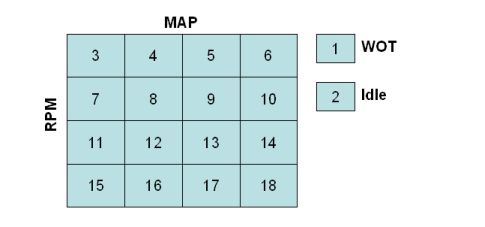
As engine operating conditions change the current zone changes
and this selects the appropriate filter equation to be used in the
dynamic airmass calculation.
Dynamic Airflow
- WOT Entry Max Airflow: If yes then set predicted airmass
to ideal (maximum) cylinder airmass when entering WOT (Zone
#1).
- MAP/TPS Airflow Filter: This filter is used to filter
the MAF airmass in response to a MAP or TPS failure. It is also
used to filter the MAF airmass when the engine RPM is greater than
the High RPM Disable limit.
- High RPM Disable: Above this RPM use filtered MAF
airmass for airmass prediction calculations.
- High RPM Re-Enable: If enabled, RPM must drop below this
to re-enable airmass prediction calculation.
- High RPM Hysteresis: Hysteresis subtracted from High RPM
Disable to re-enable dynamic airmass calculation.
- Initial Zone: Zone is initialized to this value when
engine is started.
- WOT Zone - TPS %: Throttle position greater than or
equal to this value is regarded as WOT and sets zone to #1 (WOT
Zone).
- Idle Zone - VSS: Vehicle speed must be below this to set
Idle Zone (zone #2).
- Idle Zone - TPS %: Throttle position speed must be below
this to set Idle Zone (zone #2).
- Zone RPM Boundaries: RPM boundaries that define
different zones (horizontal boundaries).
- Zone RPM Hysteresis: Hystersis applied to RPM zone
transitions to prevent oscillation between zones.
- Zone MAP Boundaries: MAP boundaries that define
different zones (vertical boundaries).
- Zone MAP Hysteresis: Hystersis applied to MAP zone
transitions to prevent oscillation between zones.
- Maximum Limit Factor:
- Deep Decel - MAP: Below this MAP activates deep decel
strategy and enables steady state.
- Dynamic Air Filter: Filters the current airmass value
before prediction filtering. If in steady state the current airmass
value is MAF based, if in unsteady state the current airmass is VE
based (using an offset based on the last calculated VE Correction
Factor).
- EGR Test Disable Time: Time to disable dynamic airmass
calculation after an EGR test.
- Cranking to Run Time: Time to transition and ramp from
cranking airmass to dynamic airmass calculations.
Prediction Coefficients
- Dynamic Airflow Corrected Gain: Dynamic airflow gain
used to calculate the corrected airmass.
- Dynamic Airflow Base Gain: Dynamic airflow gain for
calculated corrected airmass component.
- Dynamic Airflow Current Gain: Dynamic airflow gain for
current airflow from MAF or VE component.
- Dynamic Airflow Old Gain: Dynamic airflow gain for
previous airflow from MAF or VE component.
- Dynamic Airflow MAP Current Gain: Dynamic airflow gain
for current MAP component.
- Dynamic Airflow MAP Old Gain: Dynamic airflow gain for
for previous MAP component.
- Dynamic Airflow MAP Old2 Gain: Dynamic airflow gain for
second previous MAP component.
- Dynamic Airflow TPS Current Gain: Dynamic airflow gain
for current TPS component.
- Dynamic Airflow TPS Old Gain: Dynamic airflow gain for
previous TPS component.
- Dynamic Airflow TPS Old2 Gain: Dynamic airflow gain for
second previous TPS component.
Steady State
A critical part of the dynamic airmass calculation is determination
of when the engine is operating at a steady state condition or
unsteady (transient) state. During steady state the PCM uses a
filtered MAF signal as the basis for airmass calculations, the PCM
also calculates a "VE Correction Factor" during steady state. The
VE correction factor is simply the ratio of the MAF airmass to the
VE airmass and is used to "offset" the VE calculated airmass when a
transient is encountered.
During unsteady state, the PCM uses the VE table to calculate
airmass and it is offset (multiplied) by the last calculated VE
Correction factor. As long as the VE Correction factor is within
limits it will accurately offset any differences between MAF and VE
table airmasses and the transition between steady and unsteady
(transient) prediction will be smooth.
- Hi/Lo RPM Threshold: This RPM threshold determines if
High or Low steady state determination will be used. If MAP is
greater than Hi/Lo MAP Threshold or RPM is greater than Hi/Lo RPM
Threshold the High mode settings are used otherwise Low mode
settings are used.
- Hi/Lo MAP Threshold: This MAP threshold determines if
High or Low steady state determination will be used. If MAP is
greater than Hi/Lo MAP Threshold or RPM is greater than Hi/Lo RPM
Threshold the High mode settings are used otherwise Low mode
settings are used.
- Lo - MAP Delta: Low mode, MAP change below this will
enable steady state.
- Hi - MAP Delta: High mode, MAP change below this will
enable steady state.
- Lo - TPS Delta: Low mode, TPS change above this will
disable steady state.
- Hi - TPS Delta: High mode, TPS change above this will
disable steady state.
- Idle - MAP Integ Time: Time that the steady state MAP
integrator will run during the idle steady state routine before
value is compared to Integrator Threshold to disable steady
state.
- Idle - MAP Integ Threshold: If steady state MAP
Integrator exceeds this threshold during idle steady state then
steady state will be disabled.
- Idle - VSS Max: Vehicle speed must be below this to
enable idle steady state determination.
- Idle - TPS% Max: Throttle position must be below this to
enable idle steady state determination.
- Idle - MAP Int Time En: Time that the steady state MAP
integrator will run during the idle steady state routine before
value is compared to Integrator Threshold to enable steady
state.
- Idle - MAP Int Thresh En: If steady state MAP Integrator
is below this threshold during idle unsteady state then steady
state will be enabled.
VE Correction Factor
The VE Correction Factor is used to maintain a relative offset
between the VE calculated airmass and the MAF measured airmass to
ensure smooth transition between steady state and unsteady state
behavior. To protect against unstable behavior the VE correction
factor has limits in place and a reset condition.
- VE Initial Correction Factor: Initial value of the VE
correction factor, the ratio of the MAF airmass to the VE
airmass.
- VE Correction Factor - Filter: This filter coefficient
is used to filter the VE correction factor. Values closer to 1.0
mean the filtered value reacts faster to changes at the increased
risk of instability.
- VE Correction Factor - Min: Minimum limit for the VE
Correction Factor.
- VE Correction Factor - Max: Maximum limit for the VE
Correction Factor.
- VE Correction Factor - Reset: VE Correction factor will
reset to 1.0 if VE correction factor is less than this value during
deep deceleration.
- Initial ECT Boundaries: Engine coolant temperature zone
boundaries used to select initial VE correction factor value.
- Initial vs. ECT Zone: VE Correction Factor is
initialized to this value based on barometric pressure and coolant
temperature zone.